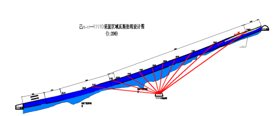
Figure 1 Single row of drill holes in the middle pumping lane of 15-17-11110
Drill hole number
Name of drill hole
Z4
Punch Z4-3-4, punch Z4-3-5, punch Z4-5-3, punch Z4-5-5, punch Z4-6-3, punch Z4-6-5,
Punch Z4-6-9, Punch Z4-7-6,
Z5
Punch Z5-2-2, Punch Z5-2-3, Punch Z5-2-5, Punch Z5-3-4, Z5-3-1, Punch Z5-3-5, Punch Z5-3-6,
Punch Z5-4-5, Punch Z5-4-4, Punch Z5-4-2, Punch Z5-5-3, Punch Z5-5-4, Punch Z5-5-5,
Punch Z5-5-7, Punch Z5-6-2, Punch Z5-6-3, Punch Z5-7-2, Punch Z5-7-3, Punch Z5-7-4
Z6
Punch Z6-1-3, Punch Z6-1-4, Punch Z6-1-7, Punch Z6-4-4, Punch Z6-4-5, Punch Z6-4-7,
Punch Z6-3-5, Punch Z6-3-4, Punch Z6-3-3, Punch Z6-2-3, Punch Z6-2-4, Punch Z6-2-8,
Z8
Punch Z8-2-3, Punch Z8-2-5, Punch Z8-2-7, Punch Z8-1-2, Punch Z8-1-3 Punch Z8-1-8,
punch z8-3-5, punch z8-3-7, punch z8-3-8, punch z8-4-3, punch z8-4-8, punch z8-4-9
Z9
Punch Z9-1-6, Punch Z9-1-7, Punch Z9-2-2, Punch Z9-2-3, Punch Z9-2-6, Punch Z9-1-4,
Punch Z9-3-3, Punch Z9-3-4, Punch Z9-3-7,
Z10
Punch Z10-1-2, Punch Z10-1-4, Punch Z10-1-9, Punch Z10-1-10, Punch Z10-2-2, Punch Z10-2-3,
Punch Z10-2-4, Punch Z10-2-5, Punch Z10-3-2, Punch Z10-3-3, Punch Z10-3-4, Punch Z10-4-2,
Punch Z10-4-3, Punch Z10-4-5, Punch Z10-5-1, Punch Z10-5-3, Punch Z10-5-5, Punch Z10-5-10,
Punch Z10-6-2, Punch Z10-6-3, Punch Z10-6-4, Punch Z10-6-5,
Z11
Punch Z11-3-1, Punch Z11-3-4, Punch Z11-3-7, Punch Z11-2-9, Punch Z11-2-4, Z11-2-1,
Punch Z11-1-2, Punch Z11-1-3, Punch Z11-1-4, Punch Z11-1-5, Z11-2-1, Z11-5-1,
Punch Z11-5-3, Punch Z11-5-6,
Z12
Punch Z12-1-6, Punch Z12-1-4, Punch Z12-1-8, Punch Z12-2-3, Punch Z12-2-4, Punch Z12-2-7,
Punch Z12-3-8, Punch Z12-3-5, Punch Z12-3-3, Punch Z12-4-3, Punch Z12-4-4, Punch Z12-4-6,
Punch Z12-5-8, Punch Z12-6-3, Punch Z12-6-5, Punch Z12-7-3, Punch Z12-7-5, Punch Z12-7-7,
Z13
Punch Z13-8-6, Z13-8-1, Punch Z13-8-5, Punch Z13-8-9, Punch Z13-9-10, Punch Z13-9-5,
Punch Z13-9-4, Z13-9-1, Punch Z13-10-8, Punch Z13-10-6, Punch Z13-10-5, Z13-10-1,
Z13-11-1, Punch Z13-11-5, Punch Z13-11-9, Punch Z13-12-3, Punch Z13-12-3, Punch Z13-12-5,
Punch Z13-12-7, Z13-13-1, Punch Z13-13-3, Punch Z13-13-5, Punch Z13-13-6, Z13-14-1,
Punch Z13-14-3, Punch Z13-14-4, Punch Z13-4-3, Punch Z13-4-4, Punch Z13-4-6, Punch Z13-4-8,
Punch Z13-3-5, Punch Z13-3-4, Punch Z13-3-3, Punch Z13-2-5, Punch Z13-2-4, Punch Z13-2-3,
Punch Z13-1-7, Punch Z13-1-6, Punch Z13-1-4, Punch Z13-1-2,
Z14
punch z14-7-9, punch z14-6-8, punch z14-6-
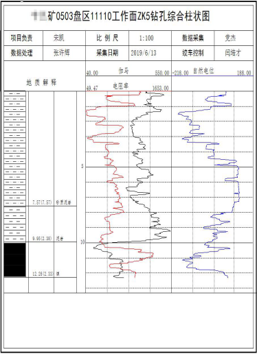
Fig. 2 Bare hole exploration results of drill hole Z5-3-4
Through the bare hole detection, we determined the condition of the coal seam bottom plate and the natural gamma change, combined with the natural gamma condition detected in the Punch Z5-3-4 pumping pipe, we obtained the results of the Punch Z5-3-4 drilling results (as shown in Figure 3-50).
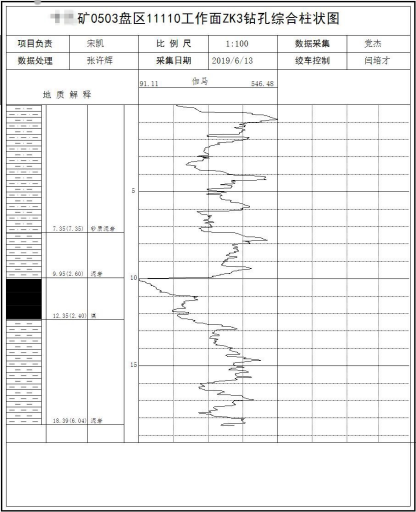
Figure 3 Drill hole punch Z5-3-4 casing exploration results map
Two fault extension zones, one coal seam relative thinning zone and one coal seam relative thickening zone were obtained through the comprehensive analysis of 191 gas pumping boreholes.
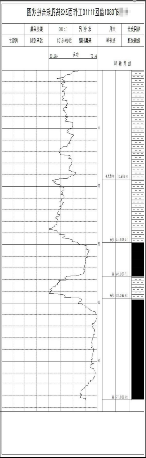
图4 冲Z8-1-8综合成果图
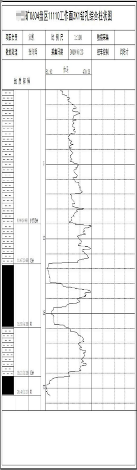
图5 冲Z6-4-4综合成果图
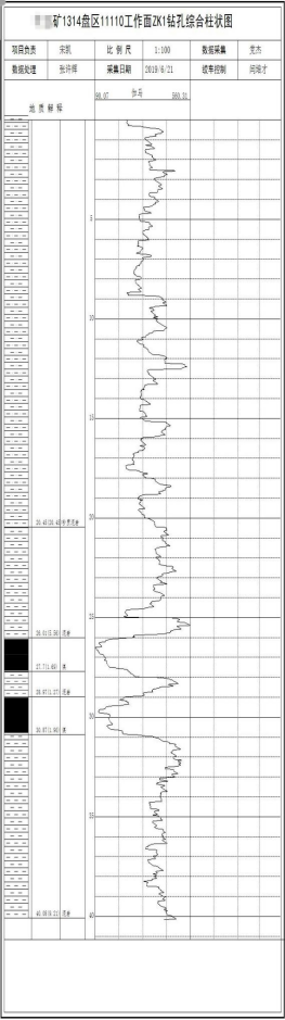
Figure 6 Z13-14-1 consolidated results map
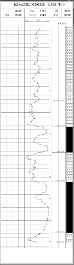
Figure 7 Z13-13-1 consolidated results map
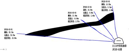
Fig. 8 Map of exploration results of row Z05-03 (blue color indicates the track, black color indicates the change of coal seam distribution)
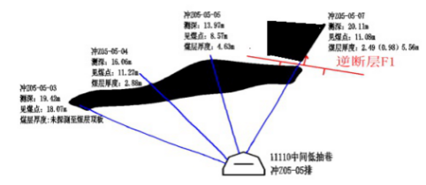
Figure 9 Map of the results of the exploration of row Z05-05 (blue color indicates the track, black color indicates the change of the coal seams, and red color is the fault)
(1) As the gas drainage holes in your mine were punched by hydraulic force, the coal section inside the holes was hollowed out, resulting in the logging work not being able to detect the top plate of the coal seam, so the construction and interpretation were carried out by using the method of detecting the location of the bottom plate of the coal seam in the bare holes and the method of correcting the detection data in the drainage pipe with the data from the bare holes;
(2) Combined with the geological data around the drill holes, reverse faults were found from row Z10-5 to row Z4-3, which were judged to be affected by the reverse fault with a drop of 5.0m exposed by the wind tunnel, and the drop of the fault gradually decreased from northeast to southwest, and the drop gradually decreased from 5.0m exposed by the wind tunnel to about 2.0m near the machine tunnel (as shown in the f9 of the result map).
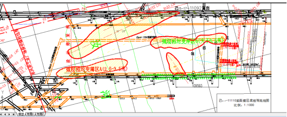
Figure 10 Drill hole logging results map
(3) Positive faults were found in rows Z13-9 to Z13-14, which were judged to be caused by the influence of the positive fault with a drop of 2.5m exposed by the machine lane (as shown in f1 in the result drawing).
(4) The thickness of the coal seam ranges from 1.9m to 7.4m, and the thickness of the coal seam varies greatly in the local area under the influence of the fault, and the relatively thinning area of the coal seam is mainly concentrated near the stopping line of the machine lane, with the thickness of 2.5m to 3.5m (as shown in A in the result drawing), while the relatively thicker area of the coal seam is concentrated in the central part of the mining face near the eye of the cut, with the thickness of more than 6.5m.


 Current position:
 Mining Video Imaging Logging Instrument